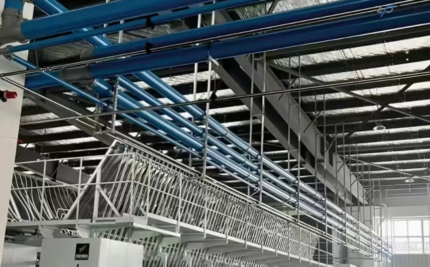
Learn how to size compressed air pipes, estimate pressure drop, account for fittings and future demand, and select an industrial aluminum piping system.
Compressed air distribution is often treated as a secondary part of a plant utility system, but the piping network can determine whether the pressure produced by the compressor actually reaches the point of use. Pipe diameter, total pipe length, fittings, valves, filters, dryers, and the layout of the main and branch lines all contribute to pressure loss. When the network is undersized, a plant may compensate by increasing compressor discharge pressure, which can increase energy use without improving the underlying distribution design.
NRCan reference point: a well-designed compressed air system should generally keep total pressure loss between the compressor discharge and the final point of use well below 10% of compressor discharge pressure. NRCan also notes that, in a reference 100 psi system, each additional 2 psi of discharge pressure can increase energy use by approximately 1% at full output.
1. Define the Design Inputs Before Choosing a Pipe Diameter
Pipe sizing should start with the system requirements, not with a preferred pipe size. At minimum, establish the following:
· Required pressure at the most remote or critical point of use.
· Peak and normal compressed air demand, preferably expressed in SCFM or another clearly defined flow basis.
· Main-line length and the longest branch-line distance.
· Number and type of fittings, valves, filters, dryers, regulators, and quick connectors in the flow path.
· Required air quality and the applicable ISO 8573-1 purity class where relevant.
· Expected production expansion and whether the distribution system will need additional drops or branches later.
Do not size the piping from compressor horsepower alone. A compressor nameplate describes the machine, while pipe sizing must account for the actual air demand and the resistance between supply and point of use.
2. Establish the Design Flow
For a preliminary design, a useful engineering framework is:
Q_design = Σ(Q_equipment × demand factor) + growth allowance
This is a planning formula rather than a universal code equation. The demand factor depends on how many pneumatic loads operate simultaneously and should be based on actual production behavior or a documented engineering assumption. NRCan notes a 20%–30% growth allowance as a practical buying consideration for compressor capacity; the corresponding pipe-system allowance should be selected according to the project rather than applied blindly.
3. Use Pressure Drop as Design Constraint
Pressure drop is the difference between the pressure available upstream and the pressure delivered downstream. In a real compressed air system, pressure loss occurs across straight pipe and across components such as elbows, tees, valves, filters, dryers and connectors. NRCan specifically warns that joints, bends and connection points create additional pressure losses and provides equivalent-length reference data for common fittings.
Engineering target: treat pressure drop as a system budget. Reserve enough pressure for the piping network so the final equipment still receives its required pressure without forcing the compressor to operate at an unnecessarily high discharge pressure.
A useful first-pass pressure budget
· Compressor discharge pressure
· Pressure loss across dryer and filters
· Pressure loss through main piping
· Pressure loss through branch piping and fittings
· Point-of-use filtration/regulation losses
· Required pressure at the equipment inlet
The design should close this pressure budget before the final pipe diameter is selected. If the calculated loss is too high, the options include increasing pipe diameter, shortening the flow path, reducing unnecessary fittings, improving the layout, or using a looped distribution arrangement where appropriate.
4. Use Published Flow Data for Preliminary Pipe Selection
Natural Resources Canada publishes an approximate reference table for airflow per 1,000 ft of pipe at a 1 psi pressure drop. These values are useful for preliminary comparisons, not for final project calculations.
Nominal Pipe Diameter | Approx. Flow at 1 psi / 1,000 ft (SCFM) |
1 in | 36 |
2 in | 263 |
3 in | 431 |
4 in | 909 |
6 in | 2,679 |
8 in | 6,757 |
10 in | 14,286 |
Reference data reproduced from Natural Resources Canada. Condition: approximate airflow per 1,000 ft of pipe for a 1 psi pressure drop. Use only as a preliminary comparison; confirm final sizing with project-specific calculations.
5. Do Not Ignore Fittings and Equivalent Length
A straight pipe calculation can look acceptable while the actual system still experiences excessive pressure loss. The reason is that every elbow, tee, valve and connection adds resistance. NRCan provides equivalent-length examples: for a 1 in nominal pipe, a 90° elbow is listed at about 2.5 ft of equivalent straight pipe; for a 4 in pipe, the same reference value is about 12 ft. These are indicators only, not project design values.
The practical implication is simple: when comparing two layouts with similar pipe lengths, the layout with fewer restrictive turns and better-planned fittings can have a lower total pressure loss.
6. Compare Branch Layouts with Loop Layouts
A single-ended branch network supplies air through one main path. A looped main creates multiple possible paths between sections of the system. For a factory with multiple production areas, a loop can help distribute flow more evenly and reduce sensitivity to a single long dead-end path, provided the pipe diameter and branch design are appropriate.
Design note: a loop does not automatically solve pressure-drop problems. The loop still needs adequate pipe diameter, balanced branches, appropriate isolation valves and a layout that reflects actual production demand.
7. Include Air Leakage in the System Review
Pipe sizing and leak management are different engineering tasks, but both affect the amount of compressed air that the plant must produce. NRCan states that it is not unusual for 20%–30% of compressor output to appear as air leaks in typical industrial facilities, and that proactive leak detection and repair programs can reduce leakage to below 10% of plant compressed-air production.
Example from NRCan: a reference example estimates the cost of maintaining a 100 cfm leak at 100 psi at about US$8,500 per year under an assumed 4,250 operating hours and US$0.10/kWh electricity cost. This is an illustrative scenario, not a universal cost figure; actual costs depend on pressure, hours, compressor efficiency and electricity price.
8. Select the Pipe Material and Connection System
Once the required diameter and layout are understood, material and connection design become part of the lifecycle decision. For industrial compressed air distribution, the key considerations include corrosion behavior, internal surface condition, connection integrity, installation method, maintenance access and the ability to expand the network.
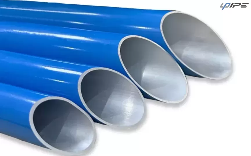
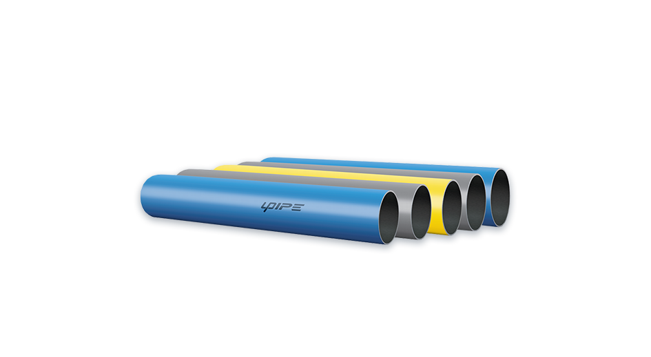
UPIPE product documentation lists its piping system for compressed air, vacuum and inert gases such as helium, nitrogen and argon, with nominal sizes from DN20 to DN200 and a listed working pressure of 16 bar. The catalog also highlights a full-size fitting design, active sealing, convex-ring clamp connection and quick-connection features.
Important: UPIPE product ratings are product-documentation values. Application engineers should verify the applicable product configuration, temperature, medium, local requirements and project conditions before specifying a system.
9. A Worked Design Example
Consider a manufacturing line with a peak design flow of 800 SCFM. The main distribution route is long enough that pressure loss cannot be evaluated from pipe diameter alone; fittings, valves and branch connections must also be included.
1. Step 1: Confirm the required pressure at the most demanding point of use.
2. Step 2: Set a pressure-drop budget for the distribution network.
3. Step 3: Use the published flow table only as a preliminary screen for candidate diameters.
4. Step 4: Add equivalent-length effects for elbows, tees and valves and calculate the full pressure drop.
5. Step 5: Compare a single-ended arrangement with a looped arrangement if multiple production areas are supplied.
6. Step 6: Check future demand, leak-management strategy and maintenance access before selecting the final configuration.
The important point is that 800 SCFM does not automatically map to one “correct” pipe size. The correct diameter depends on the allowable pressure drop, pipe length, air conditions, fitting configuration and required end-use pressure.
10. UPIPE Engineering Approach
UPIPE approaches compressed air piping as a complete distribution system rather than a collection of individual pipe sections. The product catalog emphasizes full-size fittings, active sealing, quick connection and modular configuration. These features are intended to support industrial systems where installation speed, connection reliability and future modification are important considerations.
For a project inquiry, UPIPE recommends providing the following information so the piping configuration can be evaluated more effectively:
· Compressor outlet pressure and nominal compressor capacity
· Required operating pressure at the equipment
· Peak and normal air demand
· Main-line length and floor/production-area layout
· Number of drops and major equipment connection points
· Any special air-quality, temperature or environmental requirements
· Expected future expansion or additional production lines
11. Air Quality Still Matters After Pipe Sizing
Pipe sizing does not replace air treatment. ISO 8573-1 specifies purity classes for compressed air with respect to particles, water and oil, and also identifies gaseous and microbiological contaminants. The required purity class depends on the application. Therefore, the complete system should consider compressor, dryer, filters, receiver, distribution piping and point-of-use treatment as one system.
12. Practical Checklist for Compressed Air Pipe Sizing
Check | Engineering question |
1 | What pressure must be available at the critical point of use? |
2 | What is the peak design airflow, and how much of the demand is simultaneous? |
3 | What is the allowable pressure-drop budget from compressor to point of use? |
4 | How long are the main and branch lines? |
5 | How many elbows, tees, valves, filters and connectors are in the flow path? |
6 | Would a looped distribution layout better match the plant arrangement? |
7 | What allowance is required for future expansion? |
8 | What air-quality class and environmental conditions apply? |
9 | How will leakage be detected and maintained after commissioning? |
Conclusion
Effective compressed air pipe sizing is a pressure-management problem, not simply a pipe-diameter selection exercise. The engineer must balance peak airflow, pressure-drop limits, pipe length, fittings, layout, leakage, future expansion and air-quality requirements.
The published NRCan data provides useful reference points: a well-designed system should keep total pressure loss well below 10% of compressor discharge pressure; every additional 2 psi of discharge pressure can represent roughly 1% more energy use under its reference condition; and typical industrial leakage can reach 20%–30% of compressor output. These figures show why distribution design and maintenance deserve the same attention as the compressor itself.
For industrial projects using aluminum piping, UPIPE provides a modular system covering compressed air, vacuum and inert-gas applications, with product documentation listing DN20-DN200 sizes and 16 bar working pressure. Project-specific selection should always be verified against actual operating conditions and applicable requirements.
Need help reviewing an industrial compressed air piping layout? Contact UPIPE with your airflow, pressure, pipe length and plant-layout requirements for a project discussion.