Optimize industrial airflow with practical compressed air piping design guidance covering pipe sizing, pressure loss, fittings, leakage control, and future expansion.
Compressed air distribution is often treated as a straightforward connection between a compressor and pneumatic equipment, but the piping network has a direct influence on how efficiently that air reaches every point of use. When the pipe diameter is too small, the route is unnecessarily long, or fittings introduce excessive resistance, pressure can fall before compressed air reaches the equipment that needs it. A well-planned compressed air piping design should therefore consider airflow demand, operating pressure, pipe length, pressure loss, fittings, layout, leakage control, and future capacity at the same time.
For industrial facilities, the goal is not simply to select the largest available pipe. The more practical objective is to create a distribution network that can deliver the required airflow with controlled pressure loss while remaining easy to install, maintain, modify, and expand. This becomes particularly important when production areas contain multiple pneumatic machines operating simultaneously or when additional equipment may be introduced later.
Begin With Airflow Demand Before Selecting Pipe Diameter
The first step in compressed air pipe sizing is understanding the actual airflow requirement. Pneumatic tools, cylinders, valves, actuators, packaging equipment, automation equipment, and process machinery can have very different consumption patterns. Some devices operate continuously, while others require high airflow for short periods. Looking only at the compressor capacity may therefore give an incomplete picture of what the distribution network must handle.
A useful approach is to identify the consumption of individual equipment and then evaluate how those requirements overlap. The main distribution line should accommodate the expected demand of the connected production areas rather than being sized only for one machine. If several users can operate at the same time, their combined demand becomes an important reference for determining the required pipe capacity.
Future demand should also be considered at this stage. A factory may add production stations, extend a workshop, or increase the number of pneumatic devices after the initial installation. Designing the main route only around today's consumption can create restrictions later. Allowing reasonable capacity for expansion can make the overall industrial compressed air piping design more practical over its service life.
Evaluate Pressure Loss Across the Complete Network
Pressure loss is one of the central considerations when sizing compressed air piping. As air travels through a pipe, friction between the moving air and the internal surface creates resistance. The longer the route and the higher the airflow, the more important this resistance becomes. An undersized pipe can therefore cause a noticeable pressure difference between the compressor side and the point of use.
However, pressure loss does not come only from straight pipe sections. Elbows, tees, valves, reducers, connectors, and other components also affect airflow. A network with a relatively short pipe length can still experience unnecessary resistance if the fittings are poorly selected or if the layout contains too many abrupt changes in direction.
This is why a complete compressed air piping design should evaluate the entire airflow path instead of calculating the straight pipe length alone. The objective is to maintain sufficient pressure where the equipment operates, rather than simply achieving a particular pipe diameter on paper.
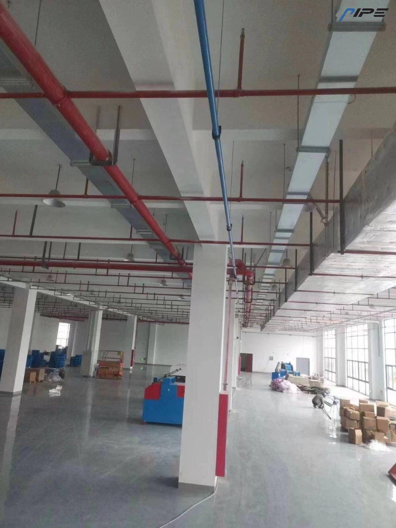
How Pipe Diameter Affects Airflow Performance
Pipe diameter determines the available internal passage for compressed air. When the diameter is reduced while airflow demand remains high, air velocity increases and friction losses can become more significant. This can make pressure regulation more difficult, particularly when multiple machines are drawing air from the same branch.
Increasing pipe diameter provides more internal flow area and can reduce resistance, but oversizing should also be approached carefully. A larger pipe requires more material and may increase installation costs without providing meaningful benefits if the actual airflow requirement is relatively low. The appropriate diameter should therefore be based on demand, distance, pressure requirements, and the overall distribution arrangement.
For this reason, compressed air pipe sizing should be treated as an engineering balance rather than a simple rule based on pipe size alone. A suitable design provides enough capacity without turning the distribution network into an unnecessarily expensive installation.
Account for Long Runs and Distribution Layout
Pipe length has a major influence on pressure loss. As the distance between the supply point and the equipment increases, the compressed air encounters resistance over a greater internal surface area. Long production halls, multi-zone workshops, and large manufacturing facilities therefore require more careful planning than compact installations.
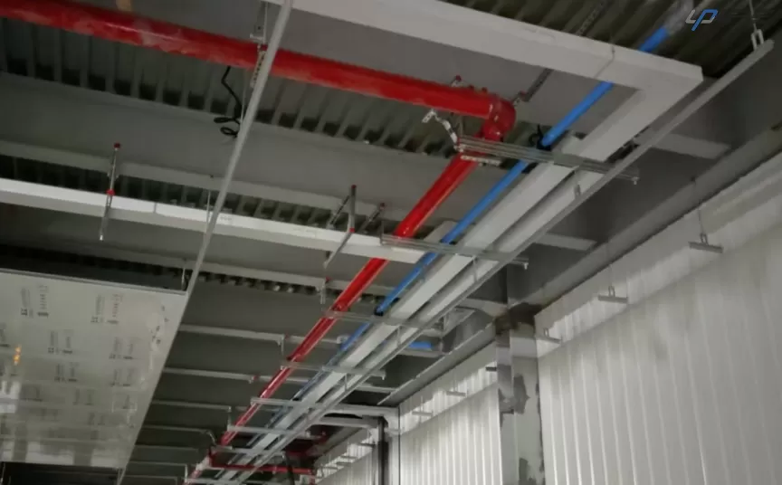
The physical arrangement of the piping should also be considered. A direct route can reduce unnecessary resistance, but the shortest route is not always the most useful one if it makes future connections difficult. A properly planned main line can serve several production areas while keeping branch lengths manageable and leaving practical connection points for additional equipment.
For larger installations, a looped distribution arrangement may also be considered when appropriate. Feeding air from more than one direction can help distribute airflow across different areas and reduce dependence on one long branch. The most suitable arrangement depends on the facility layout, demand distribution, available pressure, and expansion plans.
Do Not Ignore Fittings in the Sizing Process
Fittings can have a greater influence on airflow than their physical size suggests. Every elbow changes direction, every tee divides flow, and every valve or connector introduces another internal transition. If a piping route contains numerous fittings, their combined resistance should be considered when evaluating the expected pressure loss.
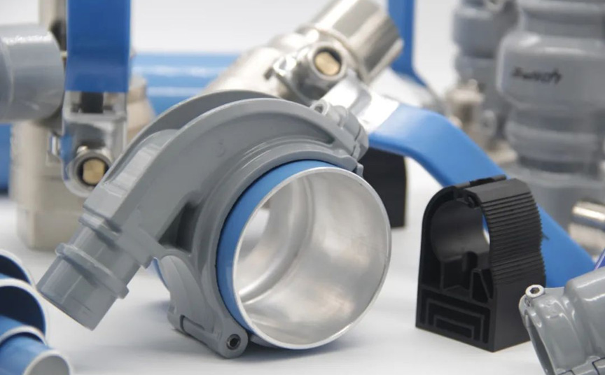
UPIPE places particular attention on the internal design of aluminum pipe fittings. Its elbows, tees, and quick drops use flow-directing structures intended to support smoother airflow and reduce unnecessary pressure loss. This is important because a piping network is only as efficient as the complete path through which compressed air travels.
Connection quality is another important consideration. Poorly sealed joints can gradually release compressed air even when the pipe diameter itself has been correctly selected. UPIPE uses integrated-molded connectors and sealing structures designed to improve connection reliability and reduce leakage associated with vibration or improper installation.
Keep Internal Surfaces Clean and Suitable for Air Distribution
The internal condition of a compressed air pipe matters because the air must travel through the network with as little unnecessary resistance and contamination as possible. Rough, dirty, or poorly protected internal surfaces can create additional concerns during installation and operation.
UPIPE aluminum pipes are manufactured from pure aluminum and are designed with clean internal surfaces. The pipe ends are precisely cut, while packaging measures help protect the internal passage during transportation and storage. These details may appear minor compared with pipe diameter, but they contribute to the overall quality of the completed compressed air distribution route.
For applications where clean compressed air is important, installation practices should maintain this cleanliness from delivery through final connection. Pipe ends should remain protected until installation, and components should be handled in a way that avoids introducing dust, debris, or other contaminants into the airflow path.
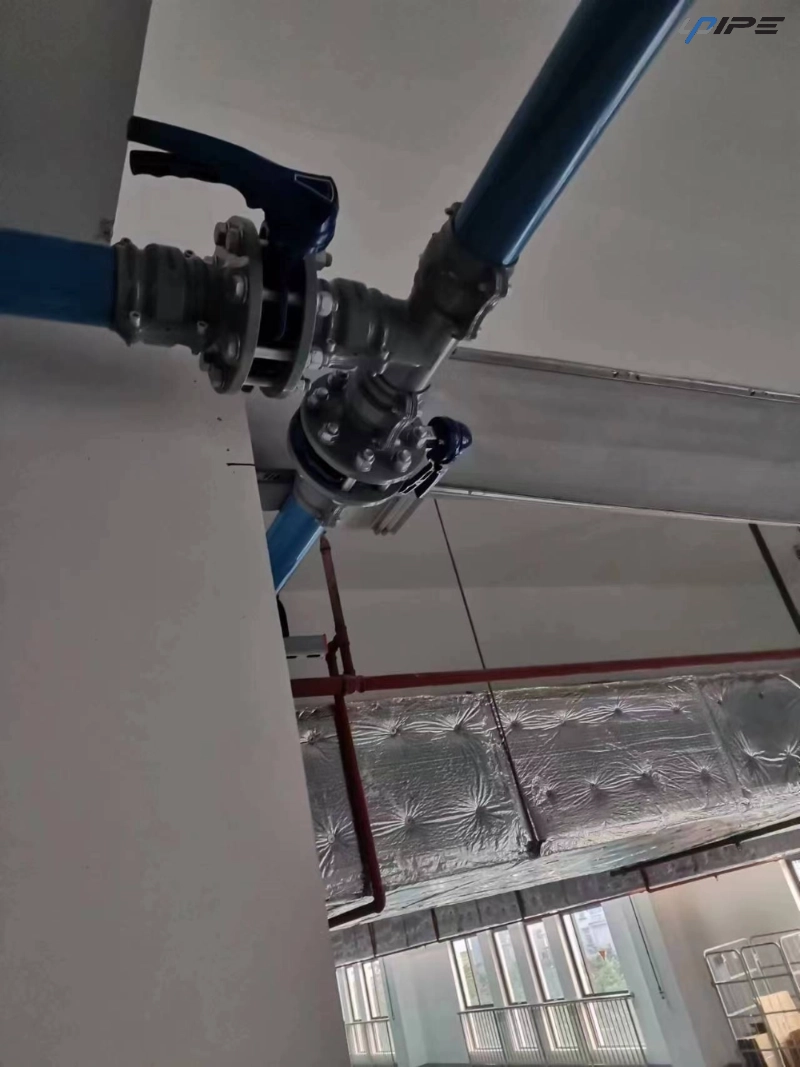
Why Aluminum Is Relevant to Compressed Air Piping Design
Material selection should be evaluated together with pipe sizing because the material affects installation, handling, durability, and long-term maintenance. Aluminum is widely used for compressed air distribution because it combines relatively low weight with good corrosion resistance and practical installation characteristics.
For industrial piping projects, a lightweight pipe can make handling and positioning easier during installation, particularly when long distribution routes or overhead pipework are involved. Aluminum also provides a smooth internal surface that is well suited to compressed air transport.
UPIPE's aluminum compressed air piping uses pure aluminum construction and thickened pipe walls to provide a combination of structural strength and practical handling. The product range also includes connectors, elbows, tees, valves, clamps, flanges, end caps, flexible hoses, and other components needed to build a complete distribution route.
Reduce Leakage Along the Distribution Route
Pipe diameter is important, but leakage can undermine the performance of an otherwise well-sized network. A small leak may seem insignificant at one connection, yet multiple leakage points across a large facility can create continuous compressed air demand. This can increase the workload placed on the air supply equipment and reduce the amount of usable air available at production points.
Leak prevention begins with connection design and continues through installation quality. Pipe ends should be prepared correctly, connectors should be installed according to their intended method, and sealing elements should remain properly positioned. Vibration should also be considered, especially around machinery where repeated movement can gradually affect connections.
UPIPE incorporates sealing structures and anti-vibration components into its piping approach. Its pipe clamps are designed to improve stability, while connector sealing features are intended to reduce the risk of leakage caused by vibration or installation issues.
Plan Quick Drops and Condensate Management Carefully
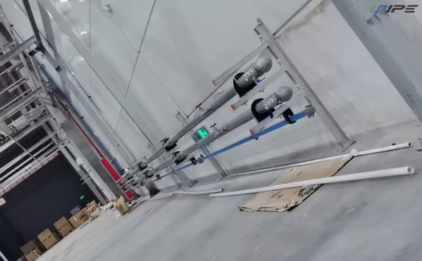
The final connection between the main distribution line and the equipment deserves separate attention. A poorly positioned branch can allow condensed moisture to move toward sensitive downstream equipment. This is particularly relevant when compressed air cools after leaving the compressor and moisture collects inside the distribution route.
Quick-drop arrangements should therefore be positioned and designed to support effective condensate management. UPIPE quick-drop components incorporate a gooseneck structure intended to help prevent condensed water from directly entering the downstream air connection. Their reinforced construction and multiple sealing surfaces also support stable connection performance.
The principle is simple: compressed air should reach the point of use through a connection arrangement that considers not only airflow but also the physical behavior of moisture inside the pipe network.
Allow Room for Future Production Expansion
A compressed air network should not be designed in isolation from the production plan. Manufacturing requirements can change over time, and additional equipment may be connected to an existing distribution line. If the original piping was sized too closely to the initial demand, expansion can lead to pressure instability or require substantial modifications.
A better approach is to consider likely future connection points when planning the main line. This does not mean automatically selecting the largest possible pipe. Instead, the design should identify areas where production may expand and provide reasonable capacity and connection flexibility.
This is particularly useful for factories where equipment layouts change frequently. A modular aluminum piping arrangement can make it easier to add branches, relocate connections, or extend the network without rebuilding the entire distribution route.
Use a Practical Sizing Workflow
A structured workflow can make compressed air piping design more consistent and easier to review. Start by listing the connected equipment and estimating the required airflow. Next, identify the operating pressure and determine the acceptable pressure loss between the supply point and the most demanding points of use.
After that, map the actual pipe route and calculate the total length, including the main line and important branches. Fittings should then be considered because elbows, tees, valves, and connectors contribute additional resistance. Finally, evaluate future demand and confirm that the selected pipe arrangement provides enough flexibility for expected changes.
| Design Stage | Main Question |
|---|
| Air demand | How much airflow is required? |
| Operating pressure | What pressure must reach the equipment? |
| Route length | How far must the air travel? |
| Pipe diameter | Can the pipe carry the required airflow efficiently? |
| Fittings | How much additional resistance will connections create? |
| Leakage control | Can joints maintain reliable sealing? |
| Expansion | Will additional equipment need to be connected later? |
This process helps prevent the common mistake of selecting a pipe diameter first and attempting to justify it afterward. In a well-developed design, the diameter is the result of several connected engineering considerations.
Installation Quality Still Matters After Sizing
Even an accurately calculated piping network can perform poorly if installation quality is inconsistent. Pipe sections should be cut cleanly, connections should be properly aligned, and clamps should provide adequate support. Unnecessary stress on joints can affect sealing performance, while poorly supported pipework can experience vibration or movement during operation.
UPIPE's product design addresses several of these installation considerations through precisely prepared pipe ends, reinforced components, anti-vibration clamps, and connection structures designed for modular assembly. For larger pipe sizes, raised rings can also help simplify connection preparation and installation work.
The final inspection should cover more than visible installation quality. Pressure behavior, connection integrity, leakage points, branch performance, and accessibility for future maintenance should all be considered before the network is placed into regular operation.
Build the Distribution Network Around Long-Term Airflow
Effective compressed air piping design is ultimately about controlling the complete relationship between airflow demand, pipe diameter, pressure loss, fittings, routing, sealing, and future capacity. A pipe that is correctly sized for one section may still perform poorly if another part of the network creates excessive restriction or leakage.
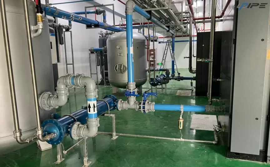
For industrial facilities, aluminum compressed air piping can provide a practical combination of lightweight construction, clean internal surfaces, corrosion resistance, modular connections, and installation flexibility. UPIPE combines these characteristics with flow-oriented fittings, sealing structures, reinforced components, and accessories designed for complete compressed air distribution applications.
The most effective approach is therefore not to focus on pipe diameter as an isolated number. Instead, evaluate the entire airflow path from the supply point to the equipment, understand how the network will operate under peak demand, control unnecessary resistance and leakage, and leave sufficient flexibility for future production requirements. This creates a more stable and maintainable compressed air distribution network while supporting efficient industrial airflow over the long term.
FAQ
How do I determine the right compressed air pipe diameter?
Start with the required airflow, operating pressure, total pipe length, acceptable pressure loss, fittings, and expected future demand. Pipe diameter should be selected after these factors have been evaluated together.
Why does pressure drop matter in compressed air piping?
Pressure drop means the pressure available at the point of use is lower than the pressure at the supply point. Excessive loss can affect pneumatic equipment performance and may increase the demand placed on the air supply.
Do fittings affect compressed air pipe sizing?
Yes. Elbows, tees, valves, connectors, and other components introduce additional flow resistance. Their quantity, geometry, and internal passage should be considered as part of the complete piping route.
Is aluminum suitable for industrial compressed air piping?
Aluminum is commonly used for industrial compressed air distribution because it offers lightweight construction, corrosion resistance, clean internal surfaces, and convenient modular installation. UPIPE provides aluminum pipes together with the fittings and accessories required for compressed air distribution.
Should compressed air piping allow for future expansion?
Yes. Future airflow demand should be considered during the initial design so that additional equipment or production areas can be connected without creating unnecessary restrictions or requiring major modifications.
What is the most important consideration in compressed air piping design?
No single factor determines the entire design. Airflow demand, pipe diameter, pressure loss, route length, fittings, leakage control, material selection, installation quality, and future expansion should be evaluated together to create a balanced industrial compressed air piping network.