Home > News > Blog > How to Design a Compressed Air Piping Network for Easy Future Expansion
# Blog
How to Design a Compressed Air Piping Network for Easy Future Expansion
2026-10-30
Share:
Design a compressed air piping network for easy future expansion by assessing demand, sizing for growth, using loop layouts, and adding isolation valves to avoid costly rework.
You save money and avoid downtime when you plan for future growth during the first design phase. Fixing things later costs far more than smart choices made upfront. Rework also disrupts production and strains your budget.
Pipes that are too small, poor layout, and weak planning are among the most common and most costly mistakes in compressed air piping. Each one limits your room to grow. Each one forces a rebuild when demand rises.
This article gives you a step-by-step process for how to design a compressed air piping network that grows without a rebuild. You will move from demand assessment to controls with confidence.
Key Takeaways
Check how much air you use now, then add 20-30% more capacity for future growth.
Pick a loop layout with shutoff valves. This keeps air pressure steady and makes it easy to add on later.
Pick pipes that are a little bigger than you need right now. This way, you won't have to pay to replace them later.
Keep the pressure drop low by fixing leaks and using fewer fittings. This saves energy.
Plan for backup systems and main controls to manage several compressors as your system grows.
Assess Demand Before You Design a Compressed Air Piping Network
Measure Today's Real Demand
Walk the production floor and list every compressed-air point of use. Then follow these steps:
Count the pneumatic tools and equipment that will connect to the network.
Get CFM or L/min ratings from nameplates or manuals at the required pressure. Do not guess.
Write down each device's minimum operating pressure. Most pneumatic tools need about 90 PSI, but some spray applications run at 100–120 PSI.
Add up the CFM of devices that could run at the same time to find peak demand.
Use a simultaneity factor: about 90% for continuous assembly, 60%–70% for intermittent batch work, and about 80% when you are not sure.
When you size the compressor later, a rule of thumb of about 4 SCFM per HP at 100 PSIG helps you check the total.
Air quality matters as much as volume. Note whether each workstation needs dry, oil-free, or filtered air, because treatment choices shape the layout you will design a compressed air piping network around. Also write down operating conditions and mounting or clearance needs for each station.
Project Growth Realistically
Build your projection from written plans, not wishful thinking. Make a table of every expected end use with its pressure, flow rate, and air quality requirement. List machinery and processes by type next to the manufacturer's stated figures.
Keep steady demand separate from intermittent demand. Write down on/off cycle times in seconds or minutes for intermittent loads. Include the number of shifts and the demand changes they cause. Add 20%–30% capacity for future expansion, and remember that oversizing the main by one diameter can cut pressure drop by about 60%.
Treat plant air for general use as its own line item, and think about keeping it separate from process air. Breathing air needs special handling. A demand profile that shows minimum, average, and peak conditions gives you a realistic baseline for growth. Check the profile again as your plans become firmer, because initial requirements will change over time.
Build In the Right Extra Capacity
Size for Growth Without Oversizing
Pipe diameter is the first place where future capacity lives or dies. When compressed air pipes are too small, air must move faster. Friction against the inside of the pipe, plus drag from elbows, tees, valves, and filters, then causes a chain of problems:
More pressure drop across the whole system
Less airflow at points of use
More work for the compressor
More energy used
Higher operating costs
Lower productivity from equipment that runs unevenly
Main lines that are too small are one of the most common industrial problems. They cause big pressure losses across the whole system. To size pipes for growth, figure out total airflow demand at today's peak flow, decide the pressure drop you can accept, measure the real pipe length with fittings, and pick the diameter from sizing charts or engineering software. Then choose a main that is a little larger at first install. That small step avoids costly system changes later.
Covers plant growth without a costly full repipe later
Energy penalty per pressure drop
~1% compressor energy increase per 2 PSI (0.14 bar)
Narrow pipes raise internal friction, so the compressor must work harder
Cost comparison
Slight oversizing now vs. full repipe in ~5 years
Sizing main headers a little larger today costs much less than replacing a bottlenecked system
Plan Compressor Capacity in Stages
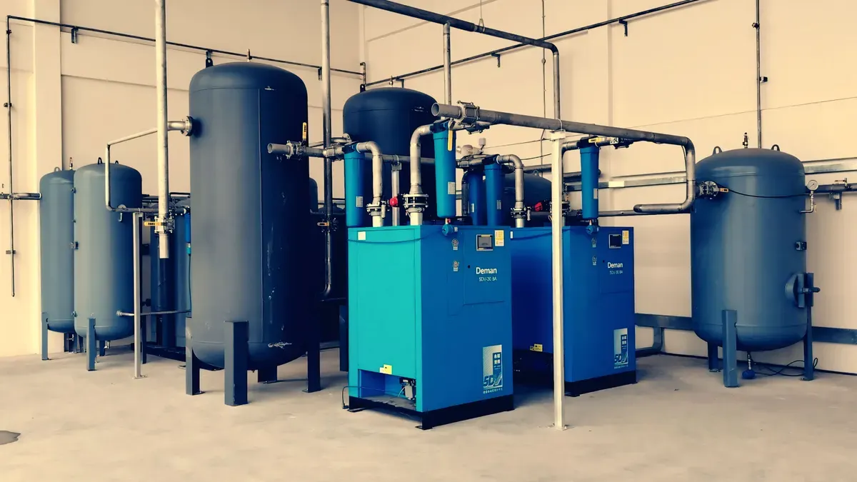
Staged capacity works better than one oversized machine. A large plant with several production areas may do better with two or three smaller rotary screw compressors instead of one oversized system. This modular setup lets you stage compressors by demand, run only what is needed during slow periods, and cut energy waste and wear. A right-sized modular system often gives better uptime, lower energy costs, and the scalability to support future growth without overinvesting upfront.
Avoid gross oversizing. An oversized compressor runs poorly at partial load, wastes energy, or cycles on and off too often. Build in a 20–30% capacity buffer to accommodate new tools, shifts, or process changes without overloading your system. You can also add extra air receiver tank volume to absorb short peaks instead of oversizing the compressor itself. Plan for 3–5 year growth with a modular approach, and think about VFD compressors, which are most efficient when load varies 40–85% of capacity.
Treat piping, storage, controls, air treatment, redundancy, and expansion capacity as one complete system. Focusing only on the compressor is a common design mistake. Extra horsepower cannot fix a distribution system that cannot move enough air. When you design a compressed air piping network this way, every part supports the next stage of growth.
A closed-loop ring layout gives you the best base for growth. You run the main pipe in a steady loop around the area where air is used. Branch pipes then drop from the loop to each workstation. Air can move either way to reach a demand point, so it takes the easiest path. This design keeps pressure steady at every drop and leaves room for new branches later.
Metric
Radial (Straight-Line) Piping
Closed-Loop Ring Main
Air flow direction
Single path
Dual-directional
Pressure drop at furthest point
High (often >1.0 bar under load)
Minimal (maintained under 0.3 bar)
Friction loss
Cumulative over full run
Distributed and minimized
System efficiency
Low (needs higher compressor discharge pressure)
High (permits lower discharge pressure)
Simultaneous tool performance
Inconsistent when multiple bays active
Consistent at all drop points
You can lower compressor discharge pressure because the loop keeps pressure steady; each 1 bar drop in needed discharge pressure means about a 6-10% cut in energy use, which saves a lot on utilities over a year of heavy commercial operation.
Size the main loop for peak simultaneous CFM demand plus a 20-30% safety margin for future growth. Longer loop runs need larger pipe diameter to keep friction losses below the 0.3 bar threshold. When you design a compressed air piping network with a loop, you get headroom that a straight-line run cannot match.
Choose Modular Piping and Isolation Valves
Place isolation valves at every zone and every major branch. This placement lets you shut down only the affected section for maintenance or expansion. Other bays stay running. Adding a drop then means isolating the section, cutting the pipe, fitting a tee, and putting the connection together. You avoid a full plant shutdown.
Zoning by usage or pressure requirement gives you better control as the network grows. Route, pipe sizes, isolation zones, valves, drains, and future connection points should be planned up front. Sectional isolation lets you close only the affected zone while another route keeps supplying critical users. For high-demand halls, you can extend the ring or build a separate zoned loop. Install accessible isolation valves and capped or valved connection points so future shutdowns become unnecessary.
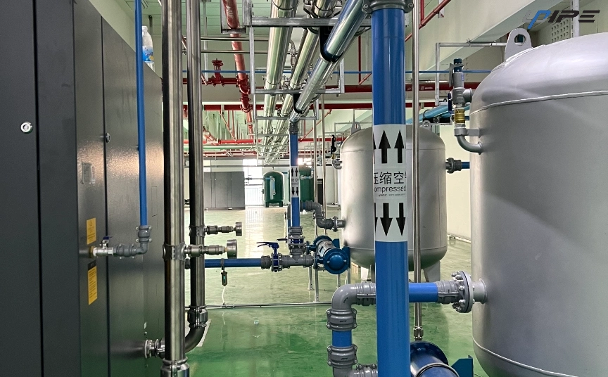
Modular piping systems make extending or changing the network easier. The Upipe Aluminum Pipe System is one option that fits this role. Its modular structure lets you add pipe sections, tees, connectors, drops, and outlets to extend the existing network. You can connect new equipment and add outlets without rebuilding the whole network. This approach suits both new construction and existing factories that need to upgrade or expand their compressed air infrastructure. Other materials also serve specific environments well, so match the choice to your site conditions.
Avoid Pressure as a Design Crutch
Fix Pressure Drop at the Source
Pressure drop takes away the extra capacity you saved for growth. If you make the piping system itself better, you keep that room for future demand. Start with these steps:
Shorter runs of compressed piping lose less pressure. Friction builds up along the length of a line, so a compact main route leaves more room for the demand you add later. Size up when your calculated demand sits near the top CFM limit of a pipe size, especially when you expect to expand.
In a straight-line layout, air has only one path from the receiver tank down the workshop. As air travels farther, friction against the pipe walls slows it and causes a steady pressure drop; a high-demand tool at the far end, used alongside other active bays, suffers a serious performance drop.
Raising pressure to cover a poor layout wastes energy and limits growth. You pay to compress air that you then throttle away, and the extra pressure puts stress on every joint and tool. Set a pressure strategy that scales instead. Design for the lowest discharge pressure that meets your tools, protect it with good routing and leak control, and check the target again as the network grows.
A setup with several units also shares the workload, which makes each compressor last longer and gives you more freedom to schedule maintenance.
Use Controls to Manage Multiple Compressors
Network controls connect all compressors into one system set up as base-load, trim, and backup units. A master control can run units from different makers in a set order and keep supply within a tight range, as low as plus or minus 2 PSIG. Sequencing modes such as FIFO, LIFO, and Equal Hours let you rotate runtime or even out hours across the group.
Controls also make expansion simple. You add a compressor to the network, and the sequencer brings it into the rotation. Plan controls, storage, and air treatment together with the piping as one system that can grow. Enough receiver storage smooths out demand spikes, and CAGI recommends eight to ten gallons per CFM of flow from the largest compressor. Size main lines for the next 5–10 years of growth, and line up dryer and filter placement with the piping layout to protect air quality and lower pressure drop.
You now have a clear plan to follow. First, check demand, then plan capacity in stages. Design the layout with loops and isolation valves. Protect pressure with good sizing and leak control. Finish with redundancy and controls that can take new compressors. Each step builds on the one before.
Designing for expansion costs little upfront. A slightly larger main or one extra valve adds only a small cost now. Retrofits after growth arrives cost far more in parts, labor, and lost production.
Plan the network before growth creates problems. Check your design against future demand before installation. When you design a compressed air piping network with growth in mind, you protect uptime and budget for years.
FAQ
How much extra pipe capacity should you add for future growth?
Add 20–30% to your peak flow when you size the main loop. A slightly larger main costs little at install. It also cuts pressure drop, so the system keeps headroom for the demand you add later.
Can you add a new air drop without shutting down the plant?
Yes, if you plan isolation valves at every zone and major branch. Close only the affected section, cut in a tee, and connect the new drop. Other bays keep running through the whole job.
Does every compressed air network need a loop layout?
No. A loop suits large halls with many drops because air travels either direction and pressure stays steady. Small or single-bay shops can run a straight main. Size either layout for the next 5–10 years of demand.
How much receiver storage should you plan for expansion?
CAGI recommends eight to ten gallons per CFM of flow from your largest compressor. Extra storage absorbs short peaks, so you avoid oversizing the compressor itself. Leave floor space for another tank as demand climbs.
When should you upgrade to a master control system?
Plan for network controls as soon as you run more than one compressor. A sequencer rotates units, holds pressure within a tight band, and brings a new compressor into rotation automatically. Add it with the piping, not after.
This website uses cookies to provide you with a safer and more personal experience. By accepting, you agree to the Cookie Policy and the use of cookies for advertising and analytics purposes.